Rotor dynamics are essential in the functioning of induction motors, which are prevalent in industrial and commercial applications. A comprehensive understanding of the rotor voltage formula not only aids in optimizing motor performance but also enhances reliability and efficiency. This becomes crucial when dealing with tasks that require precise motor control and where energy efficiency is of significant concern. The core concepts such as rotor voltage, current, and other parameters are fundamental in characterizing and predicting motor behavior.
Rotor voltage is a critical factor that influences the electromagnetic force and, subsequently, the torque produced by the motor. Similarly, rotor current is directly tied to the rotor’s ability to produce motion and dictates the overall power consumption of the motor. Apart from voltage and current, other parameters like slip, resistance, and induced electromotive force (e.m.f.) play pivotal roles in the motor’s performance. Understanding these concepts allows engineers to diagnose issues, perform maintenance, and innovate designs for better performance and energy management.
How to Calculate the Rotor Voltage of a Slip Ring Motor
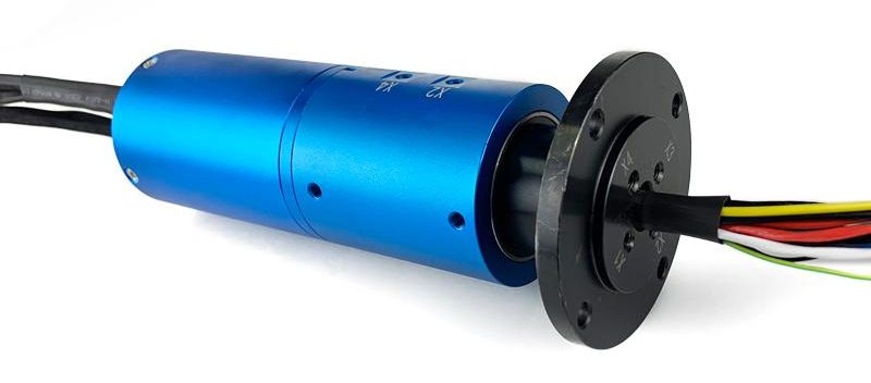
Slip ring motors are widely used in industrial applications due to their high efficiency and power output. However, calculating the rotor voltage of a slip ring motor can be a complex process. In this section, we will discuss the steps involved in calculating the rotor voltage of a slip ring motor.
Step 1: Determine the Motor’s Rated Voltage
The first step in calculating the rotor voltage of a slip ring motor is to determine the motor’s rated voltage. This can be found in the motor’s technical specifications. The rated voltage is the voltage that the motor is designed to operate at.
Step 2: Calculate the Motor’s Rotor Resistance
Once the motor’s rated voltage has been determined, the next step is to calculate the motor’s rotor resistance. This can be done by measuring the resistance of the rotor windings with an ohmmeter. The rotor resistance is the resistance of the windings when the motor is not running.
Step 3: Calculate the Motor’s Rotor Voltage
Once the motor’s rotor resistance has been calculated, the next step is to calculate the motor’s rotor voltage. This can be done by multiplying the motor’s rated voltage by the rotor resistance. The result is the motor’s rotor voltage.
Calculating the rotor voltage of a slip ring motor can be a complex process. However, by following the steps outlined in this article, it is possible to accurately calculate the rotor voltage of a slip ring motor. This will ensure that the motor is operating at its optimal efficiency and power output.
Rotor Voltage Formula through Basics of Rotor Dynamics
The role of the rotor in induction motors and the impact of the induction process on rotor performance are fundamental concepts in understanding how these motors operate. These elements are critically influenced by the rotor voltage formula, which is central to predicting and enhancing motor efficiency.
Role of the Rotor in Induction Motors
The rotor in an induction motor is the moving component that converts electrical energy into mechanical energy. It does this by interacting with the magnetic field generated by the stator. As electric currents pass through the rotor, they interact with the outer magnetic field, causing the rotor to turn. The efficiency and effectiveness of this energy conversion process are strongly influenced by applying the correct rotor voltage formula, ensuring that the rotor receives the appropriate amount of electrical energy to perform optimally.
Impact of the Induction Process on Rotor Performance
The induction process begins when a rotating magnetic field produced by the stator induces a current in the rotor. This process is governed by the rotor voltage formula, which calculates the exact voltage needed by the rotor to achieve the desired magnetic interaction. This voltage is crucial because it determines the strength and frequency of the currents running through the rotor, which in turn influences the speed, torque, and overall performance of the motor. Understanding and applying the rotor voltage formula correctly ensures that the rotor operates efficiently under various load conditions, minimizing energy wastage and improving the motor’s operational lifespan.
By delving deep into these aspects—with clear explanations of the roles and impacts shaped by the rotor voltage formula—engineers and technicians can achieve better design, diagnosis, and enhancement of induction motor performance.
Mastering Rotor Voltage Formula in Induction Motors
Understanding the rotor voltage formula in a 3-phase induction motor is pivotal for enhancing motor performance and efficiency. This formula is instrumental in determining the correct voltage applied to the rotor, which directly affects the motor’s operations.
Explaining the Rotor Voltage Formula
The rotor voltage formula is a mathematical expression used to calculate the voltage induced in the rotor of a 3-phase induction motor. This formula takes into account several factors, including the stator voltage, slip speed, and the motor’s winding characteristics. By precisely calculating the induced rotor voltage, engineers can predict the motor’s behavior under various load conditions. Proper application of the rotor voltage formula is key to ensuring that the induction motor operates within its optimal performance range.
Derivation and Significance of the Rotor Voltage Formula
Understanding the derivation of the rotor voltage formula is crucial for recognizing its significance in motor control and design. The formula is derived from the fundamental principles of electromagnetism and takes into consideration the relationship between magnetic fields within the motor and the electrical current that generates them. The significance of the rotor voltage formula lies in its ability to harmonize the motor’s electrical input with its mechanical output, thereby optimizing efficiency and prolonging the equipment’s lifespan.
Additionally, effective use of a rotor voltage formula calculator can streamline the process, allowing for quick and accurate assessments of induction motor performance. By inputting the necessary parameters, such as supply frequency, number of poles, and slip, professionals can swiftly identify the ideal voltage values required for various operational scenarios. These tools are valuable for both routine checks and complex troubleshooting tasks, ensuring that the induction motors maintain a high standard of functionality and durability.
Enhancing Performance with the Rotor Voltage Formula and Rotor Current Calculations
The rotor voltage formula plays an essential role not only in setting the voltage levels appropriate for the rotor in induction motors but also serves as a basis for calculating rotor current. Calculating rotor current using this formula is integral to assessing motor performance, ensuring optimal operation, and extending the lifespan of the equipment.
Breakdown of the Rotor Current Formula
The rotor current formula revolves significantly around the application of the rotor voltage formula. The rotor current, (I_r), can be calculated using the formula (I_r = \frac{V_r}{Z_r}), where (V_r) is the rotor voltage and (Z_r) is the rotor impedance. The rotor voltage ((V_r)) derived from the rotor voltage formula involves considerations such as the stator voltage, the slip, and other motor-specific constants. Knowing how to break down and apply these formulas correctly is crucial for electrical professionals working with induction motors.
Importance of Calculating Rotor Current
Calculating the rotor current is essential for several reasons. First, it helps engineers assess the electrical load capacity of the motor and predict its behavioral changes under different operational stresses. Secondly, it allows for the optimization of motor control, as changes in rotor current are indicative of variations in load and operating efficiency. By monitoring rotor current, potential issues such as motor overheating, inefficiency, or mechanical failures can be preempted and appropriately managed.
Example Calculation to Illustrate the Process
Consider an induction motor with a stator voltage of 400 V and a rotor impedance of 0.5 Ω, operating at a slip of 0.04. Using the rotor voltage formula (V_r = s \times V_s), where (s) is the slip and (V_s) is the stator voltage, we can calculate the induced rotor voltage:
[ V_r = 0.04 \times 400 = 16 V ]
Subsequently, using the rotor current formula (I_r = \frac{V_r}{Z_r}):
[ I_r = \frac{16}{0.5} = 32 A ]
This example showcases how the rotor voltage formula directly impacts the current flowing through the rotor, illustrating the real-world application and significance of these calculations.
By thoroughly understanding these concepts and applying them effectively, engineers and technicians ensure the reliability, efficiency, and longevity of induction motors, thereby enhancing overall system performance.
Slip in Induction Motors: Applications of the Rotor Voltage Formula
Slip in induction motors is a fundamental concept that directly influences the application of the rotor voltage formula. This section will elaborate on the definition, calculation, and impact of slip on the efficiency of the rotor, providing a deeper understanding of how induction motors operate.
Definition of Slip and Its Role in Motor Operation
Slip is defined as the difference in speed between the rotating magnetic field and the rotor itself, expressed as a percentage of the synchronous speed. This concept is crucial because it represents how far the rotor lags behind the magnetic field that drives it. Understanding slip is essential for applying the rotor voltage formula effectively since the rotor voltage depends on the slip value. Essentially, slip determines the induced electromotive force (EMF) in the rotor, which is key to the motor’s torque production and overall performance.
Formula for Calculating Slip in Induction Motors
The formula for calculating slip is given by ( s = \frac{N_s – N_r}{N_s} ) where ( s ) is the slip, ( N_s ) is the synchronous speed, and ( N_r ) is the rotor speed. By understanding this formula, one can determine how much the rotor is lagging, which is critical for effectively applying the rotor voltage formula and for adjusting the motor’s operational parameters to achieve optimal performance. Accurate calculation of slip is imperative in settings where precise motor control and efficiency are desired.
Relationship Between Slip and Rotor Efficiency
The relationship between slip and rotor efficiency is integral in motor performance optimization. Typically, a small amount of slip is necessary for the rotor to generate torque. If the slip is too high, it indicates inefficiencies such as increased resistive losses and reduced mechanical output. Conversely, a very low slip might lead to a sync-like operation but with reduced motor control and torque capability. Understanding this relationship allows for better utilization of the rotor voltage formula, ensuring that the motor operates efficiently while maintaining desired torque and speed characteristics under varying loads.
By exploring these aspects of slip in induction motors and their relationship with the rotor voltage formula, both motor designers and operators can enhance motor performance, reduce energy consumption, and extend the lifetime of their machinery. This deeper insight into motor dynamics facilitates improved design and operational strategies that lower costs and boost productivity.
The Role of Rotor Resistance in Enhancing Motor Efficiency through the Rotor Voltage Formula
Rotor resistance is a pivotal factor in the operation of induction motors, impacting their efficiency, performance, and the application of the rotor voltage formula. This section will delve into the essence of rotor resistance, its calculation, and its significance in motor diagnostics and operational efficiency.
Understanding Rotor Resistance and Its Impact on Motor Efficiency
Rotor resistance refers to the opposition a rotor circuit presents to the flow of electric current. Its value significantly influences the motor’s starting torque and speed regulation. High rotor resistance contributes to higher starting torque but can lead to greater losses and reduced efficiency during normal operation. Thus, understanding and optimizing rotor resistance is crucial for achieving a balance between high starting torque and efficient operation, a process interconnected with the effective application of the rotor voltage formula.
Rotor Resistance Formula
The rotor resistance formula, typically denoted as (R_r), is integral to calculating the precise resistance within the motor’s rotor. This formula considers various factors, including the physical characteristics of the rotor material, the rotor’s geometry, and temperature. Precise calculation of rotor resistance is essential for applying the rotor voltage formula, as the induced voltage in the rotor ((V_r)) is a function of rotor resistance and the slip according to the formula (V_r = s \cdot (R_r + jX_r)), where (s) denotes slip and (jX_r) represents the rotor’s reactance. By accurately understanding rotor resistance, engineers can manipulate motor parameters to enhance efficiency and performance.
Application of Rotor Resistance Calculations in Motor Diagnostics
Applying rotor resistance calculations is paramount in diagnostics and preventive maintenance of induction motors. Anomalies in rotor resistance can indicate potential issues such as uneven wear, short circuits, or overheating, which, if unaddressed, could lead to motor failure. By closely monitoring changes in rotor resistance, maintenance teams can preemptively identify and rectify such issues, considerably prolonging motor life and operational reliability. Moreover, integrating these evaluations with the rotor voltage formula allows for a comprehensive understanding of motor conditions and aids in the calibration of motor control systems for optimal performance.
The articulation of rotor resistance, its precise calculation, and its application in motor diagnostics are foundational to optimizing motor efficiency and reliability. Through the meticulous application of the rotor voltage formula, engineers can tailor motor operations to specific demands, ensuring both robust performance and energy efficiency.
Mysteries of Motor Efficiency with the Rotor Voltage Formula
The journey to achieving optimal performance in induction motors delves deep into the application of the rotor voltage formula, a crucial aspect in understanding and manipulating motor dynamics for enhanced efficiency. Advanced calculations and concepts such as rotor frequency, the slip ring formula, and rotor electromotive force (e.m.f.) calculation stand at the forefront of this exploration. These elements not only deepen our comprehension of motor operation but also open avenues for innovation and efficiency improvements.
Calculating Rotor Frequency and Its Impact on Motor Operation
Rotor frequency, a fundamental parameter in induction motor operation, is determined by the formula (f_r = s \cdot f_s), where (s) represents slip and (f_s) the supply frequency. This concept is pivotal as it directly influences the rotor’s induced e.m.f. and, consequently, the application of the rotor voltage formula. A precise understanding of rotor frequency enables engineers to optimize motor performance across different operational speeds, ensuring that efficiency is maximized under varying load conditions. The rotor frequency insight is not only essential for designing efficient motors but also for implementing variable frequency drives (VFDs) that adjust motor speed and torque precisely.
Slip Ring Formula in Slip Ring Induction Motors
The slip ring induction motor, known for its ability to provide high starting torque, leverages the slip ring formula to moderate rotor resistance during startup. This formula, integral to efficient motor design, adjusts the induced rotor voltage by controlling the resistance connected to the rotor circuit. The application of the rotor voltage formula here is critical, as it allows for the precise calculation of the additional resistance needed to optimize starting conditions without compromising on efficiency or causing excessive wear. By fine-tuning the slip rings and rotor resistance, these motors achieve superior performance characteristics, particularly in heavy-load starting situations.
Understanding Rotor e.m.f. and Its Calculation
The calculation of rotor e.m.f. ((E_r)) is essential for a thorough understanding of motor operation and the effective application of the rotor voltage formula. The rotor e.m.f can be theoretically derived from the formula (E_r = 4.44 \cdot \phi \cdot f_r \cdot N_r), where (\phi) represents the magnetic flux, (f_r) the rotor frequency, and (N_r) the number of rotor turns. This calculation is vital, as the e.m.f. influences the torque production and efficiency of the motor. An accurate e.m.f. calculation aids in ensuring that the motor is designed and operated in a manner that leverages the magnetic field and frequency variables most advantageously, leading to enhanced performance and lower energy consumption.
Through these advanced calculations and concepts, anchored by the rotor voltage formula, the domain of induction motor efficiency is both broadened and deepened. Engineers and technicians are equipped with the knowledge and tools necessary to optimize motor design and operation, pushing the boundaries of what is achievable in terms of energy efficiency and performance reliability.
Implementing the Rotor Voltage Formula in Practical Motor Management
When it comes to managing industrial motors, the rotor voltage formula is an essential tool that informs several practical applications critical for motor efficiency and functionality. Understanding how to calculate motor slip, compute rotor current in slip ring motors, and use rotor speed formulas to anticipate motor behavior are vital tasks for any engineer. These calculations are grounded in real-world scenarios and are invaluable for ensuring that motors operate optimally under all conditions.
Calculation of Induction Motor Slip in Real-World Scenarios
The slip of an induction motor is a measure of the difference between the synchronous speed and the actual rotor speed, and it’s crucial for the application of the rotor voltage formula. The slip is calculated using the formula ( S = \frac{N_s – N_r}{N_s} \times 100 % ), where (N_s) is the synchronous speed and (N_r) is the rotor speed. Engineers and technicians calculate slip to adjust controls, perform maintenance, or design systems for desired performance. Since slip affects the induced voltage in the rotor (as per the rotor voltage formula), accurate calculation is important for predicting motor behavior and ensuring energy-efficient operation.
Numerical Examples Demonstrating Slip Ring Motor Rotor Current Calculation
Understanding and applying the rotor voltage formula comprise an integral part of calculating rotor current in slip ring motors. A typical numerical example to determine the rotor current ((I_r)) would involve using the rated motor data, slip, rotor resistance, and reactance. For instance, given a slip ring motor with known resistance and reactance values, engineers can use the formula ( I_r = \frac{V_r}{\sqrt{R_r^2 + (s \cdot X_r)^2}} ) where (V_r) is the rotor voltage at standstill. By plugging in actual motor data and adjusting for slip using this formula, practitioners can predict the current at different operating points, which is fundamental for motor control and protection strategies.
Predicting Motor Behavior with Rotor Speed Formulas Under Various Loads
Rotor speed formulas are instrumental in understanding how an induction motor will behave under different load conditions. These formulas take into account variables such as slip and synchronous speed to determine the rotational speed of the motor. For example, the actual rotor speed can be found using ( N_r = N_s(1 – S) ), where (S) is the slip as a decimal. By using this formula, along with the rotor voltage formula, it becomes possible to predict changes in motor behavior, such as variations in torque or efficiency resulting from alterations in load. This predictive capability is key to optimizing motor performance and is especially useful for process engineering where load conditions can vary significantly.
The rotor voltage formula serves as a cornerstone for advanced motor management in industrial settings. The application of this formula through the calculation of slip, assessment of rotor current in slip ring motors, and prediction of motor behavior under various loads embodies the practical merging of theoretical knowledge with operational excellence. This ensures efficient, reliable, and predictable motor operation, which is critical to contemporary industrial processes.
FAQs on Rotor Voltage Formula
What is the equation for the rotor?
The equation for the rotor, particularly in the context of an induction motor, primarily refers to the calculation of the rotor’s induced voltage or the rotor voltage equation. The rotor’s induced voltage ((E_r)) can be described by the formula (E_r = 4.44 \cdot \phi \cdot f_r \cdot N_r), where (E_r) is the rotor induced electromotive force (e.m.f) measured in volts, (\phi) is the magnetic flux per pole in Webers, (f_r) is the rotor frequency in Hertz, and (N_r) is the number of rotor turns. This equation is critical for understanding the electromagnetic interactions within the motor, as the induced e.m.f plays a crucial role in the motor’s operation by generating torque through interaction with the stator’s magnetic field. The accurate calculation of the rotor’s induced voltage is essential for designing efficient motors and for troubleshooting purposes.
How is voltage supplied to the rotor?
Voltage is supplied to the rotor in an induction motor through electromagnetic induction, a principle discovered by Michael Faraday in the 19th century. In an induction motor, the stator carries alternating current and produces a rotating magnetic field. As this magnetic field rotates, it induces a voltage and consequently a current in the rotor conductors due to the relative motion between the magnetic field and the rotor. This process does not require physical electrical connections to the rotor; instead, the rotor receives its voltage and power through the air gap between the rotor and stator via magnetic induction. In slip ring induction motors, however, the rotor is connected to resistors or a controllable external circuit through slip rings and brushes, allowing for adjustments in the motor’s performance and characteristics.
What is the formula for the rotor power factor?
The rotor power factor ((PF_r)) in an induction motor can be described by the formula (PF_r = \cos(\theta_r)), where (\theta_r) represents the phase angle between the rotor current and the rotor voltage. This angle signifies the difference in phase between the electromagnetic force generated and the actual electrical current within the rotor winding. The power factor of the rotor is a measure of the efficiency with which the rotor converts the electric power it receives into mechanical power. It’s essential to note that a rotor’s power factor is influenced by its slip, the motor’s load, and the inherent characteristics of the motor itself. A higher power factor indicates a more efficient motor, as it implies a greater proportion of the electrical power is being used effectively to produce work.
How do you calculate rotor input power?
Rotor input power ((P_{in})) in an induction motor can be roughly estimated using the formula (P_{in} = P_{gap} / (1 – S)), where (P_{gap}) represents the power transferred across the air gap from the stator to the rotor, and (S) is the slip. The slip ((S)) is defined as (S = (N_s – N_r) / N_s), where (N_s) is the synchronous speed, and (N_r) is the actual rotor speed. This calculation takes into account the efficiency losses due to the mechanical slip between the stator’s magnetic field speed and the rotor’s actual speed. The rotor input power essentially quantifies the amount of power the rotor absorbs from the magnetic field to generate torque, discounting the power lost primarily due to rotor resistance and mechanical losses. Understanding the rotor input power is crucial for analyzing the efficiency of a motor and in the design phase to ensure optimal performance under operating conditions.