
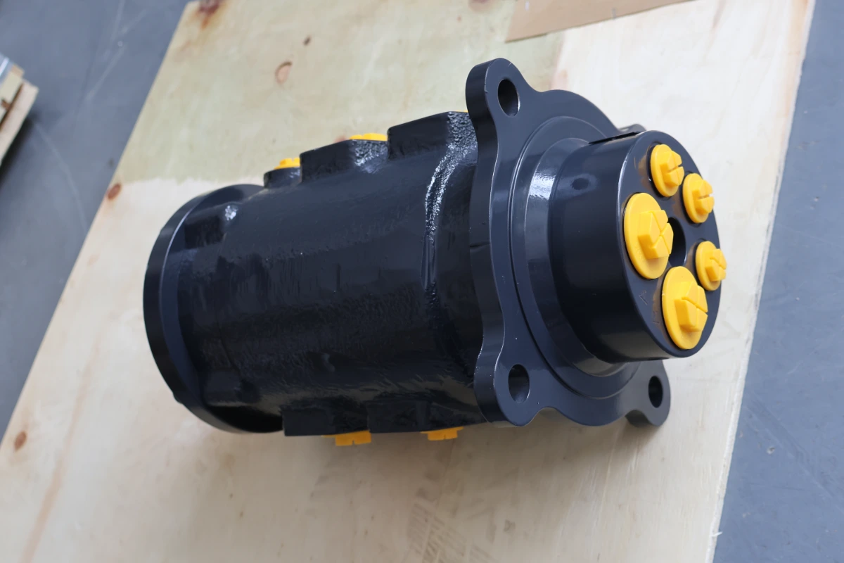
Rotary joints (also known as rotary unions) are the critical hub enabling continuous media transfer between stationary and rotating components in industrial machinery. The quality of your rotary joint installation directly dictates seal lifespan, operational stability, and unplanned production downtime. While step-by-step installation checklists are widely available, most on-site maintenance teams operate at a surface level of following procedures without grasping the failure mechanisms behind each standard. This knowledge gap leads to recurring issues including premature leakage, bearing seizure, and abnormal seal face wear.
A widely underrecognized industry truth: 70% of rotary joint performance and lifespan differences are determined at the installation stage. Routine maintenance can only slow degradation — it cannot fix inherent flaws introduced during improper setup. Many persistent “unexplained leakage” issues on the factory floor appear to stem from worn seals when disassembled, but nearly all trace back to a single non-compliant step during installation.
This guide delivers actionable, field-proven rotary union mounting best practices for industrial operations, combining full-process technical requirements, failure mode analysis, and real-world fault patterns to help you maximize equipment reliability.
Core Priorities: Concentricity Alignment & Connection Standard Compliance
The core objective of industrial rotary joint installation is to maintain high-precision coaxial alignment between the joint and the roller, while ensuring sealing integrity at all connection points. Many maintenance teams only focus on “whether the part fits” and ignore the long-term wear risks caused by concentricity deviation and mismatched connection methods. It is no exaggeration to say that calibration accuracy directly defines the upper limit of a joint’s service life.
-
Application Scenarios for Three Main Connection Types
The three mainstream connection forms — threaded connection, quick-change flange connection, and fixed flange connection — are not universally interchangeable. The long-term operation and maintenance cost caused by mismatched selection is usually 3–5 times the price of the joint itself.
- Threaded connections are suitable for low-pressure, small-bore applications requiring frequent disassembly and assembly, with low installation costs. However, they have strict requirements for thread direction matching and are not recommended for high-torque, high-vibration scenarios.
- Fixed flange connections feature strong load-bearing capacity and high sealing reliability, making them ideal for high-pressure, high-temperature, high-torque heavy-duty applications. Their drawback is low disassembly efficiency and high maintenance labor costs.
- Quick-change flange connections balance sealing performance and maintenance efficiency, and are widely used in production lines requiring regular inspection and roller replacement. However, they have higher requirements for the machining accuracy of flange spigots.
-
Fundamental Principle of Thread Rotation Direction Matching
For threaded rotary joint installations, the principle of “left-hand thread for clockwise rotation, right-hand thread for counterclockwise rotation” must be followed: when viewed from the installation side, a clockwise-rotating roller requires a left-hand thread, while a counterclockwise-rotating roller requires a right-hand thread.
The underlying logic is to use the roller’s rotation tendency to create a self-tightening effect on the threaded connection pair, preventing thread loosening during operation. If the rotation direction is reversed, the joint will gradually loosen under repeated start-stop impacts, eventually leading to leakage and even disengagement.
This failure mode has clear gradual characteristics: a joint with incorrectly matched thread direction may seal normally and show no abnormalities at the initial stage, but after approximately 3 months of frequent start-stop shocks, the thread will develop noticeable play, followed by seepage. Many sites attribute this to “thread stripping”, but it is actually an inevitable result of incorrect rotation direction matching.
-
Uniform Sealing Principle for Flange Installation
When installing flange-mounted rotary unions, bolts must be tightened gradually in a symmetric cross sequence — never unilaterally in linear order. This procedure ensures uniform compression of the sealing gasket and prevents flange warping caused by uneven stress, which would lead to local seal failure. This logic is identical to that of internal combustion engine cylinder head bolt tightening: both aim for uniform pressure across the entire sealing face.
For shaft heads or inner tube structures sealed with O-rings, apply a thin, uniform layer of compatible grease to the O-ring surface before installation. This reduces insertion resistance and prevents the O-ring from being nicked or cut by the sharp edge of the spigot. Many sites skip the greasing step and force-fit parts with impact tools; while the assembly may appear properly seated, the O-ring has already sustained micro-cuts, leading to slow, progressive leakage within 1–2 months of operation.
-
Concentricity: The Core Metric Determining Service Life
Concentricity (coaxial alignment) error is the leading cause of abnormal wear in rotary joints. Based on engineering field data, a clear conclusion can be drawn: for every 0.1 mm of concentricity deviation, seal face wear rate increases by 2–3 times, and the risk of bearing eccentric load failure rises simultaneously. When concentricity deviation exceeds 0.15 mm, service life will not reach 50% of the design rating, regardless of seal material quality.
A large share of “unexplained” periodic leakage on production lines is essentially seal face eccentric wear caused by excessive alignment deviation. This wear pattern has very distinct characteristics: abrasion is concentrated on one side of the seal face and aligns with the direction of runout. However, most facilities only replace the worn seals without addressing the root installation calibration issue, resulting in repeated failures.
The standard calibration method requires a dial indicator: mount the dial indicator on the roller end face, rotate the roller to record the upper and lower limits of radial runout, and adjust mounting bolts to center the pointer, minimizing swing during operation. Alignment verification should be performed at low speed, and all fasteners locked firmly once confirmed.
-
Commonly Overlooked Detail Requirements
For rotary joints equipped with observation (drain) ports, the port must be positioned at the 6 o’clock (bottom) position. The purpose of this requirement is to use gravity to create a minimum-delay leakage detection path. If mounted on the side, leaked fluid must accumulate to a certain level before draining, delaying leak detection by 2–5 times. If mounted at the top, the port loses nearly all warning capability, and bearings can suffer fluid damage completely undetected — this is the most insidious failure mode and carries the highest repair cost.
The threaded drain plug at the downward-facing observation port must be removed before equipment commissioning, otherwise the leakage monitoring function is completely disabled. Many new equipment startups fail to remove these plugs, allowing minor leaks to escalate into catastrophic failures that destroy both bearings and seal assemblies.
For rotary joints with bidirectional flow structures, verify the concentricity of inner and outer tubes prior to installation. Excessive inner tube length interference or out-of-tolerance fit clearances will cause operational binding and accelerated eccentric wear.
Beyond the “Consumable Mindset”: Adopt a Full-Lifecycle Approach to Rotary Joint Installation
Analysis of extensive on-site failure cases shows that most non-quality-related rotary joint failures stem from several high-frequency mistakes: omitting system flushing and filtration, calibrating alignment by hand feel, using flexible hoses as anti-rotation supports, leaving observation port plugs in place, and introducing full-temperature steam directly to cold joints. What these errors have in common is treating rotary joints as disposable commodity parts that “just need to be bolted on”, rather than precision-engineered core components requiring careful assembly.
In summary, proper rotary joint installation is not a repetitive checkbox task — it is a systematic engineering process centered on protecting the seal pair, minimizing wear rates, and extending reliable operation cycles. Behind every installation specification lies a defined failure mode. Only by moving beyond superficial rule-following and understanding the technical logic behind each requirement can you truly optimize installation quality, reduce equipment failure rates at the source, and improve the operational efficiency and profitability of your production lines.
See What We Can Do