Introduction
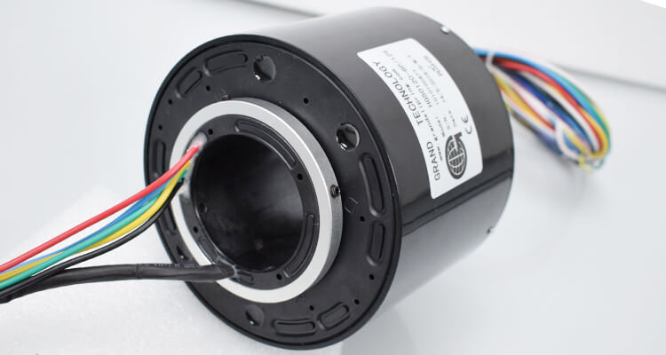
Slip rings are devices that play a pivotal role in varying industries including medical imaging, aerospace, defense, and manufacturing, among many others. They are also referred to as rotary electrical interfaces, rotating electrical connectors, swivels, collectors, or electric swivels. Notably, the underlying premise of a slip ring is to enable the transmission of power and electrical signals from a stationary unit to a rotating object. This amazing feat allows continual 360-degree rotation without the hindrance of tangled wires.
Among many different specifications and parameters associated with slip rings, one significant component known for its functionality is the Outer Diameter (OD) or more commonly, the Slip Ring OD. Measured in millimeters or inches depending on the locale, the OD is an essential factor that governs the design and operation of the slip ring. It has direct implications on the amount of current that can be transferred, the complexity of signal communication, and the overall size and format of the slip ring.
The choice of the right Slip Ring OD is dependent on a multitude of factors including application requirements, design constraints, and operational performance. Thus, it is crucial to have a comprehensive understanding of Slip Ring OD to make the right choice for achieving optimal operation. This article aims to elucidate the concept of Slip Ring OD, discussing its importance, aspects of choosing the right OD, its implications on slip ring performance, and tips to keep in mind while purchasing a slip ring.
What Is Slip Ring OD?
When discussing the components and dimensions of a slip ring, one critical parameter is the Outer Diameter or the Slip Ring OD. This measurement refers to the total distance across the slip ring through its central point, which gives the size of the slip ring from one end to the other while passing through the center.
In terms of structural design, the OD plays a fundamental role because it determines how much space is available for the incorporation of various components within the slip ring. This might include a house for conductive rings, circuits, and wires. These elements are the core carriers of power and signals – the more space for these vital components, the more robust the power or signal transmission capabilities of the slip ring can be.
The dimension of the Slip Ring OD can widely range, from just a few millimeters to several meters based on its intended face of application. For instance, a large OD, which hypothetically means a larger slip ring, can accommodate more circuits or enhance the current-carrying capacity. It’s important to remember this isn’t always feasible or beneficial because increasing the size can lead to other design challenges.
On the contrary, where space is at a premium, such as aerospace or medical applications, a smaller OD would be more appropriate. However, this also means a compromise on the number of circuits or the amount of power that can be transmitted through the slip ring. Therefore, there’s a constant juggling and striking a balance between spatial constraints and operational needs when deciding on the Slip Ring OD.
Understanding the concept of Slip Ring OD and how it influences the slip ring’s operational capacity can guide engineers, manufacturers, and consumers toward making a more informed decision in the selection and utility of slip rings.
How to Choose the Appropriate Slip Ring OD?
Choosing the appropriate Slip Ring OD is a task that involves careful consideration of various factors that directly impact the slip ring’s performance in its intended application. Here are several factors that should be considered:
Understanding Your Application Needs
The first step is to have a clear perspective of your application requirements. What will the slip ring be used for? How much power or how many signal varieties does it need to transfer? For instance, applications that require more circuits or high-power transmission may need a larger OD to accommodate more wires and conductive rings.
Consider the Mechanical Space Constraints
The available space and mechanical limitations greatly influence the choice of OD. Slip rings with larger ODs may not fit well into compact spaces. Hence, it’s essential to ensure that the chosen OD fits neatly within the mechanical size constraints of your application.
Operational Speed
Higher rotational speeds and larger ODs may not always be compatible. This is because larger diameters result in higher centrifugal forces at increased rotational speeds, which can adversely affect the slip ring’s reliability and lifespan. Hence, the operational speed must be considered in light of the slip ring OD.
Balancing Performance with Size
An ideal slip ring will balance the need for high performance with practical size constraints. For instance, disk-type slip rings can have a large OD providing ample space for circuits, but may not be suitable for high-speed applications due to increased centrifugal forces. Therefore, it’s necessary to seek the right balance between size and functionality.
Customizability
Sometimes, standard ODs might not meet specific application requirements. In such cases, look for manufacturers that offer customization options where the OD can be scaled to your exact needs.
By keeping these factors at the forefront, one can make a well-informed decision when selecting a slip ring. Balancing the trade-offs among the OD, performance capabilities, operating speed, and the application’s space constraints can drive toward an optimal choice.
Application of Slip Ring OD with Different Values
The Outer Diameter (OD) of a slip ring is a crucial factor that influences its appropriate selection depending on the intended application. Slip rings with different OD values are applied across myriad sectors to meet specific functional requirements. Here are a few examples of their applications.
Miniature Slip Rings
Known for their compact size, miniature slip rings often have an OD ranging from a few millimeters. These are commonly used in applications where space is limited yet functionality cannot be compromised. Common uses can be found in medical devices like endoscopes or microscopic cameras where small OD slip rings transmit power and signals into highly compact spaces.
Mid-size Slip Rings
These slip rings feature an intermediate OD and find applications in sectors such as automotive manufacturing, wind power generators, and robotics. These industrial applications often require moderate power transmission, and multiple circuits for signal passing with higher rotation speeds, making mid-size OD slip rings the perfect fit.
Large Industrial Slip Rings
Frequently used in heavy-duty industrial applications like large wind turbines and cranes, large industrial slip rings can feature an OD of several meters. They offer high power transmission, greater current carrying capacity, and can accommodate numerous circuits for complex signal transmission.
Disk-type Slip Rings
Disk slip rings typically hold a larger OD which allows them to house more circuits in a relatively slim form. These are often used in applications where vertical space is constrained, such as in CCTV systems, or in rotary tables favoring a flat design.
Capsule Slip Rings
With an OD range typically between 12.5mm to 54mm, these kinds of slip rings are popular in sectors needing reliable transmission in a compact design. Common applications include speed dome cameras and rotary sensors.
Each OD value is tailored to specific use cases and has its advantages and constraints. Thus, careful consideration of the operational environment and the functional requirements is necessary when choosing from different Slip Ring OD values.
Slip Ring OD and Slip Ring Short Circuit
The Slip Ring OD holds a significant influence on avoiding short circuits in slip ring assemblies. Short circuits can occur when electrical current flows through an unintended pathway, bypassing the proper circuit or conductive pathway, and causing damage or malfunction to the slip ring.
With a larger OD, there is generally more space to work with, which means more room for the layout and placement of wires and conductive rings. This increased space allows for better segregation of the wires and circuits, reducing the risk of short circuits caused by contact between adjacent conductive elements. The increased space can also accommodate thicker insulation layers between individual circuits, ensuring a higher degree of overall electrical safety and isolation.
To mitigate the risks associated with short circuits, the following factors should be carefully managed:
Circuit Segregation: Proper spacing between the conductive elements reduces the chances of unintentional physical contact, leading to short circuits. A larger Slip Ring OD allows for better spacing, thus reducing overlap risks.
Insulation Methods: The insulating materials and methods employed in the slip ring assembly should be compatible with the voltage levels and rotational speed requirements of the application. An appropriately chosen Slip Ring OD can ensure there’s enough space for the required insulation.
Manufacturing Quality: High-quality manufacturing standards and properly chosen materials can reduce the likelihood of irregularities that might lead to short circuits. Ensure the slip ring manufacturer adheres to industry quality standards and uses appropriate materials.
Maintenance Practices: Regular maintenance and inspection of slip rings can identify any signs of wear or damage that might lead to short circuit issues. This preventative approach can help in prolonging the slip ring’s lifespan and mitigate potential problems.
In conclusion, the Slip Ring OD directly impacts the slip ring’s ability to ensure proper circuit segregation and insulation, ultimately reducing the chances of short circuits. Choosing a Slip Ring OD with careful consideration of the application’s requirements can minimize the risk of short circuits and boost overall system safety and reliability.
Slip Ring OD Data of Different Types of Slip Rings
The Outer Diameter (OD) of different types of slip rings can vary significantly based on their application requirements. Here are a few examples:
Through Hole Slip Ring
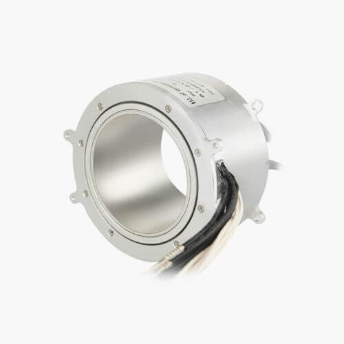
Through hole slip ring is a kind of slip ring with a hole in the center. Same meaning as a through-bar slip ring, sometimes called a hollow shaft slip ring. Through hole slip ring totally meets with continuous transmission of power, signals, weak current, high current, and high voltage under 360-degree unrestrained rotations. Low torque, low electrical noise, low loss, and easy maintenance as the main features.
The process of manufacturing and principle are similar to other slip rings. Power, signals, and other data are transmitted from the fixed position to the rotating position through the contact between the brush and the contact. Gold brush and contact will increase the working life. The basic technical parameters of a hole/bore slip ring mainly include bore outer diameter, bore inner diameter, length, circuits, voltage, current, maximum speed, etc. The length is variable and can be customized arbitrarily, while the outer diameter and inner diameter have some standard dimensions in through hole electrical slip rings industry. The number of circuits is the one core parameter for this series of products, the larger the number of circuits, the more complex the manufacturing process, and the higher the price cost.
Model | Picture | No. of Rings | ID(mm) | OD(mm) | Rated Current | Rated Voltage | |
1-12 | 12 | 33 | 2A | 0~240V | |||
1-24 | 12 | 54 | 5A | 0~240V | |||
1-10 | 20 | 60 | 2A~10A | 0~380V | |||
1-48 | 25.4 | 78 | 2A~10A | 0~380V | |||
1-48 | 38.1 | 99 | 2A~15A | 0~380V | |||
1-10 | 50 | 75 | 2A~12A | 0~380V | |||
1-72 | 50 | 120 | 5A~20A | 0~380V | |||
1-96 | 60 | 135 | 5A~20A | 0~380V | |||
1-96 | 70 | 155 | 5A~20A | 0~380V | |||
1-96 | 80 | 180 | 5A~20A | 0~380V | |||
1-96 | 90 | 190 | 5A~20A | 0~380V | |||
1-96 | 100 | 203 | 5A~20A | 0~380V | |||
1-96 | 120 | 250 | 5A~20A | 0~380V | |||
1-96 | 150 | 300 | 5A~20A | 0~380V | |||
1-96 | 180 | 332 | 5A~20A | 0~380V | |||
1-96 | 200 | 350 | 5A~20A | 0~380V | |||
1-96 | 250 | 407 | 5A~20A | 0~380V | |||
1-96 | 300 | 490 | 5A~20A | 0~380V | |||
1-96 | 400 | 632 | 5A~20A | 0~380V |
Ethernet Slip Ring
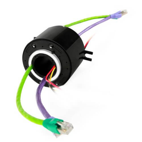
Ethernet slip rings are slip rings with Ethernet connectors that allow to transmission of Ethernet protocol through a rotating interface. Ethernet hybrid slip rings run power, signal, and Ethernet from stationary structures to rotating platforms through copper or gold channels. Can mix electrical power and signals, and also transmit multi-channel low-frequency signals and currents.
Ethernet slip ring suitable for 10/100/1000 Base T transmission and usually equipped with RJ45 connector assemblies for plug and play. M12, CAT5E, or CAT6 cables are available as options. Gigabit ethernet slip rings can be used in wind turbines, industrial robots, and radar antennae which need rotary platforms.
Pancake Slip Ring
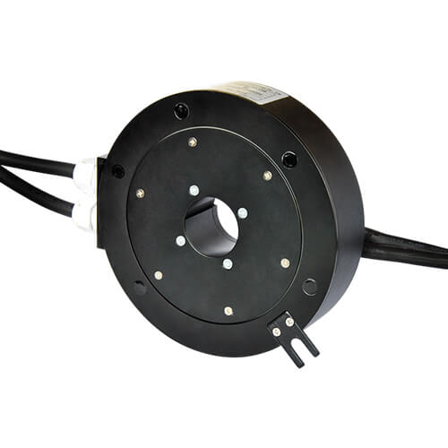
The pancake slip ring is similar to through through-hole slip ring but is especially used for the rotating system with a height limit. Also called flat slip ring, flat disc electrical slip ring, or platter slip ring, since the shape is similar to a platter, rings, and brushes contact around the center of the circle. Pancake slip ring components include stator, rotor, and contacts, mainly used for transmitting precise signals and power or combined with pneumatic and hydraulic media. More electrical power, current, and signal circuits can extend broadwise limitless on flat diameter.
Pancake slip rings can be configured in two types, integrated and separated.
Integrated ring types can be designed for solid or through-hole rotating systems.
The separated ring type is composed of a separated rotor and contact brush, which can be designed with PCB.
High Temperature Slip Ring
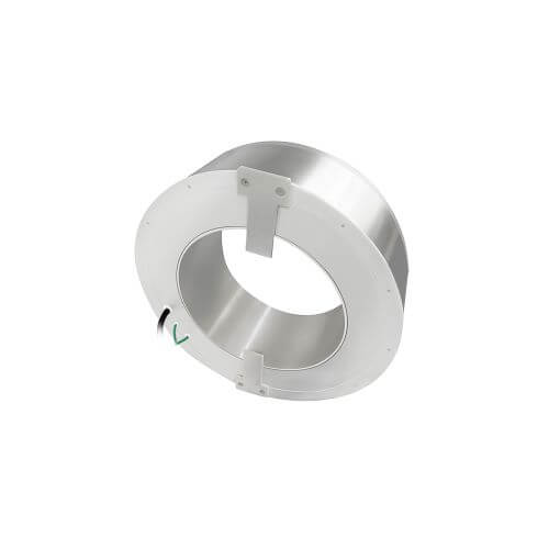
The slip ring can work stably under a 100~250℃ high-temperature environment, even above 250℃.
Model | No. of Rings | ID(mm) | OD(mm) | Rated Current | Rated Voltage | |
1-12 | 12.0 | 33.0 | 2A | 0~240V | ||
1-24 | 12.7 | 54.0 | 5A | 0~240V | ||
1-10 | 20.0 | 60.0 | 2A~10A | 0~380V | ||
1-48 | 25.4 | 78.0 | 2A~10A | 0~380V | ||
1-48 | 38.1 | 99.0 | 2A~15A | 0~380V | ||
1-72 | 50.0 | 120.0 | 5A~20A | 0~380V | ||
1-96 | 60.0 | 135.0 | 5A~20A | 0~380V | ||
1-96 | 70.0 | 155.0 | 5A~20A | 0~380V | ||
1-96 | 80.0 | 180.0 | 5A~20A | 0~380V | ||
1-96 | 90.0 | 190.0 | 5A~20A | 0~380V | ||
1-96 | 100.0 | 203.0 | 5A~20A | 0~380V | ||
1-96 | 120.0 | 250.0 | 5A~20A | 0~380V | ||
1-96 | 150.0 | 300.0 | 5A~20A | 0~380V | ||
1-96 | 180.0 | 332.0 | 5A~20A | 0~380V | ||
1-96 | 200.0 | 350.0 | 5A~20A | 0~380V | ||
1-96 | 250.0 | 407.0 | 5A~20A | 0~380V | ||
1-96 | 300.0 | 490.0 | 5A~20A | 0~380V | ||
1-96 | 400.0 | 632.0 | 5A~20A | 0~380V |
USB Slip Ring
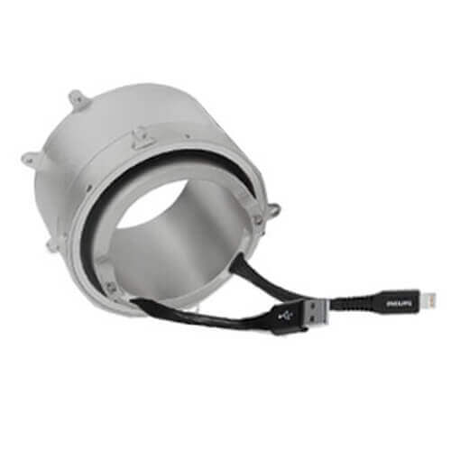
A USB slip ring is specially designed to transmit USB1.0/USB2.0/USB3.0 signals through a rotating interface. USB 2.0 slip rings are widely used in all kinds of communication systems since the USB interface is very popular and convenient for HD video and super-large storage devices. The new generation slip ring for standard USB 3.0 provides a theoretical transmission rate of 5Gbps.
High Speed Slip Ring
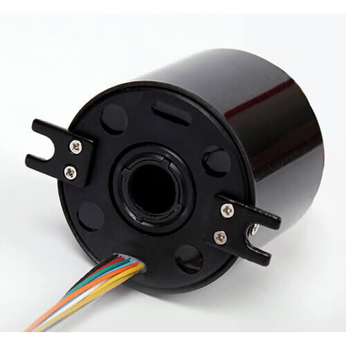
A slip ring can reach 2000 rpm and work stable, even above 4000 rpm.
Model | No. of Rings | ID(mm) | OD(mm) | Max Speed | |
3 | -- | 12 | 800 rpm | ||
10 | 8 | 54 | 2000 rpm | ||
10 | 20 | 78 | 2000 rpm | ||
10 | 35 | 99 | 2000 rpm | ||
10 | 45 | 120 | 2000 rpm | ||
10 | 55 | 135 | 2000 rpm | ||
18 | -- | 30 | 2000 rpm | ||
36 | -- | 33 | 2000 rpm |
High Voltage/High Current Slip Ring
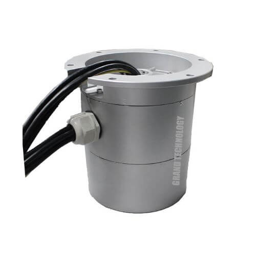
High Voltage/High Current Slip Ring are used for communication devices, large machining centers, antenna radar systems, large cranes, mining machines, and large cable reels. High voltage sometimes requires more than 2,000 volts and high current sometimes requires 500 amperes.
Model | ID(mm) | OD(mm) | No. of Rings | Max Rated Current | |
50 | 135 | 4 | 280A | ||
66 | 202 | 20 | 500A | ||
70 | 176 | 8 | 100A | ||
75 | 185 | 98 | 1000A | ||
75 | 190 | 4 | 400A | ||
80 | 180 | 3 | 250A |
Waterproof Slip Ring
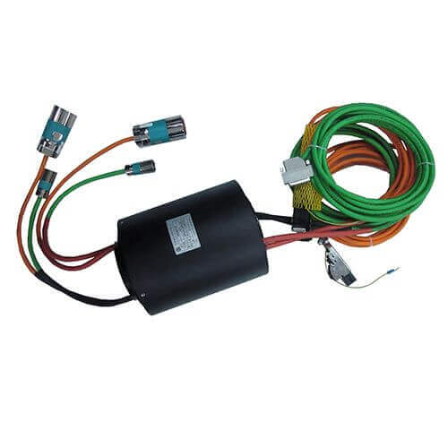
A waterproof slip ring is especially for working under moisture, corrosion, and underwater. The protection grade will be IP65, IP67, and IP68, and the liquid components in the working environment such as freshwater, seawater, oil should be considered. Waterproof slip rings are widely used in ships, harbor equipment, and some water or moisture environment working conditions. The units work well for transmitting precision signals, and electrical power.
CAN Bus Slip Ring
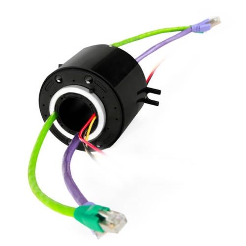
The industrial bus type mainly solves the digital communication between the field equipment such as intelligent instruments, controllers, and actuators in the industrial field, as well as the information transfer between these field control equipment and the advanced control system. The bus design will directly affect the performance, reliability, expansibility, and upgradability of the whole microcomputer system.
Servo Encoder Slip Ring
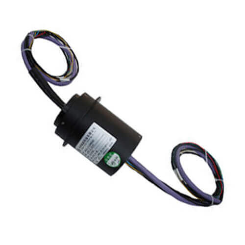
The servo encoder slip ring is an electrical slip ring that works for the servo encoder signal and servo motor power supply. The servo encoder slip ring can save many cables and installation works to transmit data and power. Suitable for all kinds of servo/stepper motors. Supplies usually use gold contacts to avoid external interference and internal interference.
Capsule Slip Ring
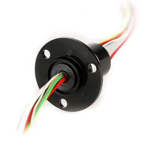
Capsule slip rings are often offered in a compact size with flange-like miniature slip rings, used for electrical power transmission and data transfer between a stationary and a rotating part. Capsule Slip Rings also have the rotor, stator, brush block, bearing, and housing. They are easily installed and widely used in small and medium-sized equipment, such as speed dome cameras, intelligent toys, stage lights, drones, etc.
Miniature Slip Ring
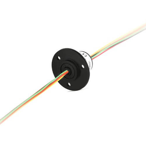
A miniature slip ring assembly is specially designed for small installation spaces. Also called a small slip ring, mini slip ring, compact slip ring, or micro slip ring. A miniature slip ring is the extension of a capsule slip ring through the bore slip ring. The miniature package units have been designed to offer an economical and compact solution for signal and power transmission between the rotor and stator side. Shaft or flange are the two main mounting methods.
PIN Slip Ring
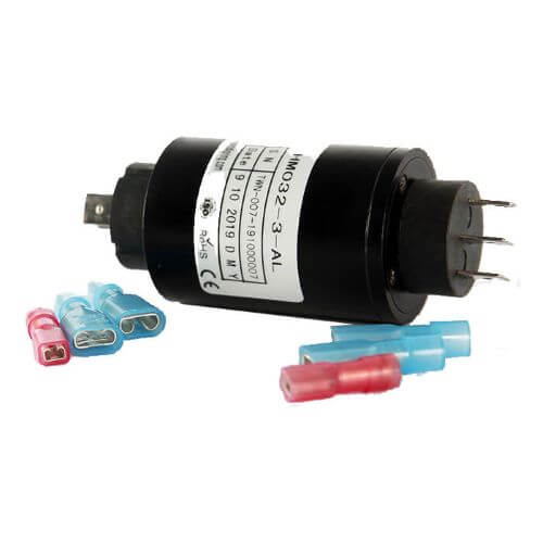
PIN slip rings are the substitute for mercury slip rings. Mercury slip rings use liquid metal mercury as the transmission medium. Special sealing technology, insulation, and compact design made them outstanding features like extremely long working life, low electrical noise, and contact resistance. Mercury is a chronic toxic substance. There have great potential threat to both the environment and the operators if leaked. People have been actively searching for alternative products.
Model | Picture | No. of Rings | OD(mm) | Rated Current | RPM | IP | |
2 | 32 | 20A | 0~400 | IP54 | |||
2 | 32 | 20A | 0~400 | IP65 | |||
2 | 32 | 20A | 0~400 | IP68 | |||
3 | 32 | 5A/20A | 0~400 | IP54 | |||
3 | 32 | 5A/20A | 0~400 | IP65 | |||
3 | 32 | 5A/20A | 0~400 | IP68 | |||
4 | 32 | 5A/20A | 0~400 | IP54 | |||
4 | 32 | 5A/20A | 0~400 | IP65 | |||
4 | 32 | 5A/20A | 0~400 | IP68 | |||
5 | 32 | 5A/20A | 0~400 | IP54 | |||
5 | 32 | 5A/20A | 0~400 | IP65 | |||
5 | 32 | 5A/20A | 0~400 | IP68 |
HDMI Slip Ring
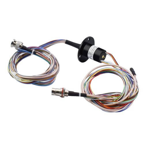
HDMI slip ring is based on an HDMI connector and transmits data and power between the rotor side and the stator side. HDMI and 3G-SDI slip rings provide the best solutions for transferring high-definition images and voice in a rotating system. Widely used in broadcast television, photography, and video as well the new technology like VR.
Model | No. of HD-SDI | Frequency rate | Power Rings | Signal Rings | OD(mm) | |
1 | DC-1.5 GHz | 4 | 30 | 25 | ||
3 | DC-1.5 GHz | 4 | 28 | 25 | ||
1 | DC-3 GHz | 3 | 20 | 54 | ||
1 | DC-3 GHz | 3 | 20 | 78 | ||
1 | DC-3 GHz | 3 | 20 | 99 |
Fiber Optic Rotary Joint
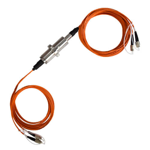
The fiber optic rotary joint (FORJ) is also called the fiber optic slip ring. Optic rotary joints FORJ help to transmit optical communication, like electrical slip rings are used to transmit electrical power and signals. FORJ provides a connection for uninterrupted transmission of optical signals across rotating interfaces. It is especially good for high-speed data transfer on many applications. The key parameters are Insertion Loss, Insertion Loss Variation, and Return Loss.
RF Rotary Joint
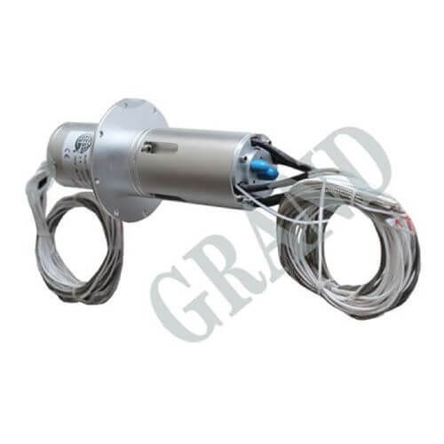
RF rotary joint is the abbreviation of radio frequency, used to transmit radio frequency signals between rotor and stator parts in a rotary system. RF rotary joints can be divided into three types, coaxial rotary joints, waveguide rotary joints, and waveguide to coaxial rotary joints. The possible applications range from radar antennae to military, air traffic control, and space. It is often necessary to receive and send multiple-frequency signals.
Model | Frequency Rate(GHz) | No. of RF Channels | No. of Electrical Rings | OD(mm) | |
DC-18 | 1 | -- | 14.22 | ||
DC-4.5 | 2 | -- | 32 | ||
DC-4.5 | 2 | -- | 122 | ||
DC-18 | 1 | 11 | 54 | ||
DC-4.5 | 2 | 12 | 80 | ||
14-14.5 | 2 | 5 | 122 | ||
14-14.5 | 2 | 15 | 180 |
These are merely typical ranges and actual values can differ substantially based on the manufacturer and specific application requirements. Moreover, it’s noteworthy that many manufacturers also offer custom OD options where slip rings can be tailored as per the exact requirements.
Buying Tips about Slip Ring OD
Choosing the correct outer diameter (OD) for a slip ring is crucial for its effective operation. The following are some key points to keep in mind when making your selection:
Assess Your Application Needs
First and foremost, understand the specific demands of your application. Evaluate the power or types of signals that need to be transmitted, the desirable number of circuits, the operating speed, and other technical requirements to help you determine the exact OD you need. Larger ODs generally allow more room for circuits and power transmission, but this should be balanced with other needs.
Understand Space Constraints
Always remember to consider the mechanical and spatial constraints of your application. Evaluate the space where the slip ring will be installed; a larger OD may not always be the best choice for compact spaces. Make sure the chosen OD suits your space without compromising the functionality.
Evaluate Operational Speeds
Typically, larger ODs can affect the reliability and lifespan of the slip ring at higher operational speeds due to the greater centrifugal forces generated. Therefore, it’s necessary to consider the operational speed your application requires against the OD of your slip ring.
Balance Performance with Size
Come to an ideal compromise between the OD size and performance. While larger OD may house more circuits, it may not suit high-speed applications due to the increased centrifugal force. Therefore, a balance between size (OD) and functionality is crucial to ensure that it fits your requirements.
Check for Customizability Options
If the standard OD sizes do not meet your specific application requirements, look for manufacturers that offer customization options. This will allow you to scale the OD as per your needs and enhance the flexibility of your application.
Remember: an informed purchase is a smart purchase. Your focus on these critical points will enable you to choose the right slip ring OD and ensure that your application operates efficiently and effectively.
Conclusion
The Slip Ring OD plays a vital role in the slip ring’s overall performance, susceptibility to short circuits, and the amount of data it can handle. Balancing the size of the OD, along with proper insulation and circuit segregation, can ensure a safer and more robust operation in various applications. However, it’s essential to consider other factors such as operational speeds and spatial limitations, as larger ODs can have a trade-off in suitability for high-speed environments due to increased centrifugal forces.
In conclusion, understanding and properly determining the appropriate Slip Ring OD for your specific use case is crucial for the successful implementation of slip ring-based assemblies. Ensuring an optimized selection, focused on both functionality and spatial requirements, will contribute to reliable and efficient operation, minimal risk of short circuits, and an extended lifespan for your equipment.
FAQ About Slip Ring OD
Q: What is the significance of Slip Ring OD in its operation?
A: The Slip Ring OD determines the capacity to transmit power, the number of circuits, and the slip ring’s insulation. It also plays a crucial role in design and implementation.
Q: How does OD affect the choice of slip ring for an application?
A: The choice of Slip Ring OD will depend on various factors, including the mechanical constraints of the application, the desired performance or signal transmission capacities, and the operational speeds.
Q: Can the Slip Ring OD be altered?
A: The OD of a specific slip ring is usually fixed as determined by the manufacturer. However, companies can often customize slip ring ODs as per customer requirements.
Q: What is the effect of OD on speed?
A: A larger OD may increase the centrifugal forces at high rotation speeds, which could impact the reliability and lifespan of the slip ring.
Q: What happens if I choose the wrong OD for my slip ring?
A: Choosing the wrong OD could cause multiple issues including mechanical interference, insufficient power or signal transmission capabilities, short circuit issues, and reduced reliability or lifespan.
See What We Can Do

